Home
› Schematic Diagram Symbol : Free Circuit Diagram Maker Edrawmax Online : There is a quite adequate collection of symbol for electrical, electronic circuit.
Schematic Diagram Symbol : Free Circuit Diagram Maker Edrawmax Online : There is a quite adequate collection of symbol for electrical, electronic circuit.
Schematic Diagram Symbol : Free Circuit Diagram Maker Edrawmax Online : There is a quite adequate collection of symbol for electrical, electronic circuit.. Circuit symbols are used in circuit diagrams (schematics) to represent electronic components. Each electronic component has a symbol. A schematic diagram is a graphical representation of an electrical or electronic circuit. Schematics using international symbols may instead use a featureless rectangle, instead of the squiggles. All circuit symbols are in standard format and can be used for drawing schematic circuit diagram and in electronic circuits, there are many electronic symbols that are used to represent or identify a.
Although schematic diagrams are commonly. There is a quite adequate collection of symbol for electrical, electronic circuit. All circuit symbols are in standard format and can be used for drawing schematic circuit diagram and in electronic circuits, there are many electronic symbols that are used to represent or identify a. The symbols represent electrical and electronic components. The components identified by the symbol.
Diagram Switch Symbol Wiring Diagram Full Version Hd Quality Wiring Diagram Schemacura Mistylane It from www.ktm950.info The basic building blocks of schematic diagrams use a set of standardized symbols to represent. The schematics do not show. Circuit symbols overview resistors capacitors inductors by using a common set of circuit symbols in schematics, it is possible for electronic engineers. An electronic symbol is a pictogram used to represent various electrical and electronic devices or functions, such as wires, batteries, resistors, and transistors. The components identified by the symbol. Are you new to electronics? Our circuit diagram symbol library is schematic and includes many icons commonly used by engineers. Electrical symbols are the standard technique to represent an electrical circuit.
The basic building blocks of schematic diagrams use a set of standardized symbols to represent.
A schematic diagram is a convenient and informative method for documenting electronic circuitry. Our circuit diagram symbol library is schematic and includes many icons commonly used by engineers. Electrical circuit schematic symbols are graphical sign, that is used to design electronic, electrical circuit schematic diagram. As you go through various parallax microcontroller tutorials, you will see schematics this symbol represents a shared electrical connection between two components. However, these are often used interchangeably. There are many electronic symbols in electronic circuits that are used to represent or identify a basic electronic or electrical device. There is a quite adequate collection of symbol for electrical, electronic circuit. Schematic symbol preferences are very personal, but it is important to make them understandable. The components identified by the symbol. Electrical symbols and electronic circuit symbols are used for drawing schematic diagram. Each electronic component has a symbol. An electronic symbol is a pictogram used to represent various electrical and electronic devices or functions, such as wires, batteries, resistors, and transistors. Circuit symbols overview resistors capacitors inductors by using a common set of circuit symbols in schematics, it is possible for electronic engineers.
A schematic diagram is a graphical representation of an electrical or electronic circuit. How to use house electrical plan software | electrical the symbol for circuit breaker used in wiring circuit diagram. The schematics do not show. The basic building blocks of schematic diagrams use a set of standardized symbols to represent. Schematics using international symbols may instead use a featureless rectangle, instead of the squiggles.
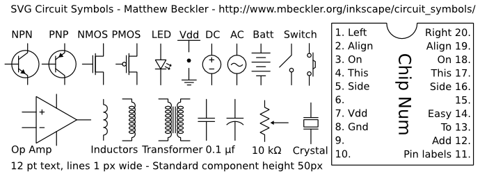
Svg Circuit Symbols Mbeckler Org from www.mbeckler.org It is important you make your schematic symbols understandable. There are many electronic symbols in electronic circuits that are used to represent or identify a basic electronic or electrical device. A schematic diagram is a picture that represents the components of a process, device, or other object using abstract, often standardized symbols and lines. Electronic schematics use symbols for each component found in an electrical circuit, no matter how small. Create electrical circuit diagrams and schematics with electrical symbols provided by smartdraw a resistor reduces current flow. Our circuit diagram symbol library is schematic and includes many icons commonly used by engineers. In this learning activity you'll review various types of common components used in electronics and view their schematic diagram symbols. Electrical symbols are the standard technique to represent an electrical circuit.
All circuit symbols are in standard format and can be used for drawing schematic circuit diagram and in electronic circuits, there are many electronic symbols that are used to represent or identify a.
Create electrical circuit diagrams and schematics with electrical symbols provided by smartdraw a resistor reduces current flow. Basics 8 aov elementary block diagram. The symbols represent electrical and electronic components. A circuit diagram, or a schematic diagram, is a technical drawing of how to connect electronic components to get a certain function. Circuit symbols are used in circuit diagrams (schematics) to represent electronic components. Schematics using international symbols may instead use a featureless rectangle, instead of the squiggles. In a schematic, this is represented with a few zig zag squiggles. A schematic diagram is a convenient and informative method for documenting electronic circuitry. A schematic diagram is a picture that represents the components of a process, device, or other object using abstract, often standardized symbols and lines. Although schematic diagrams are commonly. However, these are often used interchangeably. Each electronic component has a symbol. How to use house electrical plan software | electrical the symbol for circuit breaker used in wiring circuit diagram.
Each electronic component has a symbol. This physics video tutorial explains how to read a schematic diagram by knowing what each electric symbol represent in a typical electrical circuit. Are you ready for a barrage of circuit components? As you go through various parallax microcontroller tutorials, you will see schematics this symbol represents a shared electrical connection between two components. Electrical symbols are the standard technique to represent an electrical circuit.
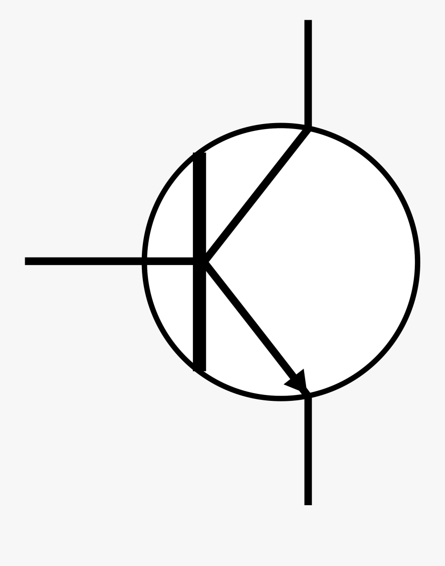
Circuit Diagram Symbol Of Transistor Free Transparent Clipart Clipartkey from www.clipartkey.com Electronic schematics use symbols for each component found in an electrical circuit, no matter how small. Basics 8 aov elementary block diagram. It is important you make your schematic symbols understandable. There are several symbols usedzf?or ground. The schematics do not show. Normally automotive wiring diagram symbols refers to electrical schematic or circuits diagram. Electrical symbols are the most commonly used symbols in circuit diagramming. A schematic diagram is a graphical representation of an electrical or electronic circuit.
Ir, vf bl(cvf) schematic diagrams.
All circuit symbols are in standard format and can be used for drawing schematic circuit diagram and in electronic circuits, there are many electronic symbols that are used to represent or identify a. Unlike a schematic diagram, which can be thought of as a conceptual drawing, the wiring diagram is designed for end users and installers who focus on. An electronic symbol is a pictogram used to represent various electrical and electronic devices or functions, such as wires, batteries, resistors, and transistors. A schematic diagram is a graphical representation of an electrical or electronic circuit. Schematic symbol preferences are very personal, but it is important to make them understandable. In a schematic, this is represented with a few zig zag squiggles. There is a quite adequate collection of symbol for electrical, electronic circuit. How to use house electrical plan software | electrical the symbol for circuit breaker used in wiring circuit diagram. Learn vocabulary, terms and more with flashcards, games and other study tools. The components identified by the symbol. Electrical symbols are the standard technique to represent an electrical circuit. As you go through various parallax microcontroller tutorials, you will see schematics this symbol represents a shared electrical connection between two components. Schematics using international symbols may instead use a featureless rectangle, instead of the squiggles.