Home
› Power Amplifier Circuit Diagram : 100W MOSFET power amplifier - The Circuit : This is linear power amplifier 2000 watt which need advance knowledge in electronics since the schematic diagram is very complex for hand made circuit.
Power Amplifier Circuit Diagram : 100W MOSFET power amplifier - The Circuit : This is linear power amplifier 2000 watt which need advance knowledge in electronics since the schematic diagram is very complex for hand made circuit.
Power Amplifier Circuit Diagram : 100W MOSFET power amplifier - The Circuit : This is linear power amplifier 2000 watt which need advance knowledge in electronics since the schematic diagram is very complex for hand made circuit.. Alarm, amplifier, digital circuit, power supply, inverter, radio, robot and more. One of the clocks is wired as an astable multivibrator to produce the. Pusher look at the two transistors n1 and p1 works, n1 consisting of common collector amplifier circuit for amplifying the input pulse voltage signal positive half cycle; I have been looking for a good stereo amplifier circuit diagram for a long time. Two darlington power transistors are arranged in a class ab configuration to amplify the power level of this signal.
Description this is a 19 watt simple amplifier circuit diagram using ic la4440 from sanyo. Comparing the typical circuit schematics in fig 8 and 9 it is easy to see why the new single cycle control requires a fraction of the design effort compared. Find free all about power amplifier circuit design and more ideas in here, that most tested power amplifier circuit from guest and admin. A transistor configured in class a. Circuit diagram of a three stage practical audio power amplifier is shown in the figure below.
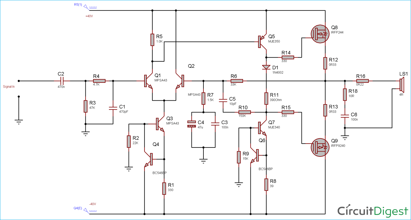
Circuit Diagram for 100 Watt Power Amplifier Circuit using ... from circuitdigest.com One of the clocks is wired as an astable multivibrator to produce the. Discrete class ab transistor audio power amplifier circuit diagram. Circuit diagram of a three stage practical audio power amplifier is shown in the figure below. The circuit (first diagram) utilizes double clock ne556 to create the sound. Initially, there are two type of amplifier circuit diagram is in practical i.e. This is a like full 1000w power amplifier circuit diagram. Assemble the circuit on a good quality pcb. ■ high output power capability:
We can watch the video of this circuit board:
That's mean this circuit uses two ic's of every single channel in bridge mode. This amplifier has four pieces of power ic tda7294. The circuit (first diagram) utilizes double clock ne556 to create the sound. A transistor configured in class a. Transistor circuit diagram with protector. I have been looking for a good stereo amplifier circuit diagram for a long time. Center tap transformer for transistor amplifier. Circuit diagram of a three stage practical audio power amplifier is shown in the figure below. Click here for all circuit diagrams. Simple 5.8w audio power amplifier circuit designed with very few external parts, this circuit constructed based on it has adjustable closed loop gain and high sustaining over voltage with high power and low distortion output. Comparing the typical circuit schematics in fig 8 and 9 it is easy to see why the new single cycle control requires a fraction of the design effort compared. Preamplifier circuit diagram for power amplifier. How to repair amplifier circuit.
A power amplifier circuit is used to drive the loads like speakers with minimum output impedance. Alarm, amplifier, digital circuit, power supply, inverter, radio, robot and more. Preamplifier circuit diagram for power amplifier. Audio power amplifier is an amplifier which produces amplification of power between the input and output. This amplifier has four pieces of power ic tda7294.
500W Power Amplifier 2SC2922, 2SA1216 with PCB Layout ... from 3.bp.blogspot.com Audio power amplifier is an amplifier which produces amplification of power between the input and output. Savesave 500w power amplifier circuit diagram for later. This stereo amplifier circuit diagram is cheap and simple. This amplifier has four pieces of power ic tda7294. One of the clocks is wired as an astable multivibrator to produce the. There are eleven transistors, including four in the output stage. I have been looking for a good stereo amplifier circuit diagram for a long time. Transistor circuit diagram with protector.
As you can see in the above block diagram, power amplifier is the last stage which is directly connected to the load.
Tda7294 is a monolithic integrated circuit in multiwatt15 package, with high output power (up to 100w) intended for . tda2030 is a monolithic integrated circuit in pentawatt package, intended for use as a low frequency class ab . Description this is a 19 watt simple amplifier circuit diagram using ic la4440 from sanyo. Small signal transistor q1 and its associated components form the voltage amplification stage. The amplifiers are classified based on the applied signals either it is the voltage signal or the power signal. Audio power amplifier is an amplifier which produces amplification of power between the input and output. 1000 watt amp circuit diagram, wzmacniacz schemat. .circuit diagram 200w power amplifier circuit diagram hi fi amplifiers amplifier circuit diagram power amplifier circuits power amplifier high power amplifier pdf rf amplifier stereo amplifier circuit diagram sound amplifier circuit pcb design software audio power amplifier car power. And the output of power amplifier dc voltage contains approximately 63. Transforms is a electrical energy from one circuit to another without any direct electrical connection. Voltage amplifier circuit and power amplifier circuit. This amplifier has four pieces of power ic tda7294. Alarm, amplifier, digital circuit, power supply, inverter, radio, robot and more. This is linear power amplifier 2000 watt which need advance knowledge in electronics since the schematic diagram is very complex for hand made circuit.
Preamplifier circuit diagram for power amplifier. A transistor configured in class a. Tda7294 is a monolithic integrated circuit in multiwatt15 package, with high output power (up to 100w) intended for . tda2030 is a monolithic integrated circuit in pentawatt package, intended for use as a low frequency class ab . Transforms is a electrical energy from one circuit to another without any direct electrical connection. Power supply circuit diagram shown as follow:
Power Amplifier APEX H900 - Efficient, Flat and Powerful ... from 1.bp.blogspot.com And the output of power amplifier dc voltage contains approximately 63. Find free all about power amplifier circuit design and more ideas in here, that most tested power amplifier circuit from guest and admin. Discrete class ab transistor audio power amplifier circuit diagram. Audio power amplifier is an amplifier which produces amplification of power between the input and output. In this audio/power amplifier circuit design tutorial, we will build a 100w rms output power amplifier using mosfets and transistors with a 4 ohms impedance speaker connected to it. Power supply circuit diagram shown as follow: This is linear power amplifier 2000 watt which need advance knowledge in electronics since the schematic diagram is very complex for hand made circuit. Click here for all circuit diagrams.
Transforms is a electrical energy from one circuit to another without any direct electrical connection.
This stereo amplifier circuit diagram is cheap and simple. Transistor circuit diagram with protector. The last circuit was added on thursday, november 28, 2019.please note some adblockers will suppress the schematics as well as the advertisement so please disable if the schematic list is empty. Alarm, amplifier, digital circuit, power supply, inverter, radio, robot and more. As practical operational amplifier techniques became more widely known, it was apparent that these feedback. 0 ratings0% found this document useful (0 votes). I am not a hifi geek, i just wanted to build a simple stereo amplifier that could drive some speakers for my desktop computer. This amplifier has four pieces of power ic tda7294. The amplifiers are classified based on the applied signals either it is the voltage signal or the power signal. Initially, there are two type of amplifier circuit diagram is in practical i.e. This is tda7294 rms 300w amplifier circuit diagram. Assemble the circuit on a good quality pcb. P1 is also composed of common collector amplifier circuit for amplifying.