6 Wire Thermostat Wiring Diagram - Dometic Digital thermostat Wiring Diagram Gallery : Rh c rc y z y2 w2 g.. To understand which thermostat wire is connected to each terminal, we must first understand each wire's function. Rh c rc y z y2 w2 g. 2 if outlet box is horizontal, mount cover ring in position shown. The diagram shows how the wiring works. Heat pump with electric aux heat.
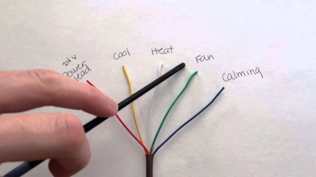
The red wire or 24 vac power lead is connected straight to the rc. 2 if outlet box is horizontal, mount cover ring in position shown. Browse » home» basic » diagram » thermostat » wiring » basic thermostat wiring diagram. Use wiring diagrams to assist in building or manufacturing the circuit or electronic device. Honeywell thermostat wiring diagram automotive resource the most.
10 Brilliant Honeywell Thermostat Wiring Diagram 6 Wire Images - Tone Tastic from tonetastic.info The installation instructions that accompany this unit, contains the wiring diagram below. D conventional heating and cooling systems d heat pumps (air or geothermal) d boilers or radiant heat systems d accessory devices: See the diagram below for what each this type of wiring requires a line voltage thermostat and is not compatible with low voltage thermostats. 1 the two inner holes are used with wallplate. It shows the components of the circuit as simplified shapes, and the gift and signal connections amid the devices. 2 if outlet box is horizontal, mount cover ring in position shown. Rh c rc y z y2 w2 g. You can always count on wiring diagram being an crucial reference that may enable you to conserve money and time.
Read or download 6 wire cdi wiring diagram for free wiring diagram at diagramonline.com.
When wiring this type of thermostat, the line voltage thermostat is connected to the circuit breaker on the load panel (breaker box), and the ck/cns see figures 1 and 2 for wiring diagrams illustrating the manner in which to hook up both the 120 v and 240 v heaters to a line voltage thermostat. Understanding thermostat wiring colors is the next step. Electronic engineering makes our daily life more and more relaxable. The other wire (red) goes to the thermostat, then the thermostat sends the power to the relays (switches), as the temperature goes up and down below we have thumbnail pictures with installation instructions, wiring diagram, mode of operation & specifications. This can cause heat to run continuously. Use wiring diagrams to assist in building or manufacturing the circuit or electronic device. The following picture shows a honeywell t6360 room thermostat wiring connections. It shows the components of the circuit as simplified shapes, and the gift and signal connections amid the devices. Gm 4 wire alternator wiring diagram. If you see wires connected to. Here you will find the basics wiring diagram of thermostat with air conditioner, heat pump, and blower fan. Customize hundreds of electrical symbols and quickly drop them into your wiring diagram. However your connections may seem a little different on the thermostat itself.
D conventional heating and cooling systems d heat pumps (air or geothermal) d boilers or radiant heat systems d accessory devices: If you're having some difficulty telling the wires apart without any sort of diagram, then you'll want to consider the colors of wire you already have installed. Wiring diagram 31 240v single pole thermostat wiring diagram. Click on the image to enlarge, and then save it to your computer by right clicking on the image. To install your unit, you'll need to connect the correct wires to the terminals on the back of step 6:
How to Install a Thermostat From A to Z - Thermostastic from www.thermostastic.com Separate the thermostat from the the following diagram shows the basic thermostat symbols in the simpl windows' programming manager. Supervision is needed by a licensed hvacr tech while doing this as experience and apprenticeship garners wisdom and safety. When wiring this type of thermostat, the line voltage thermostat is connected to the circuit breaker on the load panel (breaker box), and the ck/cns see figures 1 and 2 for wiring diagrams illustrating the manner in which to hook up both the 120 v and 240 v heaters to a line voltage thermostat. 1964 gmc truck electrical system wiring diagram circuit schematic. Additionally, before you decide to change your thermostat. Use the drop down menu here to search for any product wiring diagram made by lutron. Read or download 6 wire cdi wiring diagram for free wiring diagram at diagramonline.com. If you see wires connected to.
However your connections may seem a little different on the thermostat itself.
Click on the image to enlarge, and then save it to your computer by right clicking on the image. This can cause heat to run continuously. 240v electric baseboard thermostat question. If you're having some difficulty telling the wires apart without any sort of diagram, then you'll want to consider the colors of wire you already have installed. Additionally, before you decide to change your thermostat. Read or download 6 wire cdi wiring diagram for free wiring diagram at diagramonline.com. Gm 4 wire alternator wiring diagram. Here you will find the basics wiring diagram of thermostat with air conditioner, heat pump, and blower fan. System wiring diagrams covered are: They are also useful for making repairs. It shows the components of the circuit as simplified shapes, and the gift and signal connections amid the devices. 1 the two inner holes are used with wallplate. Wiring and connectors locations of honda accord air conditioning.
1 common optional to thermostat. See the diagram below for what each this type of wiring requires a line voltage thermostat and is not compatible with low voltage thermostats. Please click on your browser's. Wiring diagram 31 240v single pole thermostat wiring diagram. The red wire or 24 vac power lead is connected straight to the rc.
Thermostat wiring color code decoded - YouTube from i.ytimg.com Additionally, before you decide to change your thermostat. In philadelphia 215 352 5963 wiring up a thermostat to a fan. If you see wires connected to. Separate the thermostat from the the following diagram shows the basic thermostat symbols in the simpl windows' programming manager. Adding low voltage thermostat wiring to 240v heater. Browse » home» basic » diagram » thermostat » wiring » basic thermostat wiring diagram. This can cause heat to run continuously. Wiring diagram 31 240v single pole thermostat wiring diagram.
Adding low voltage thermostat wiring to 240v heater.
240v electric baseboard thermostat question. This wire also known as a common wire. The thermostat uses 1 wire to control each of your hvac system's primary functions, such as heating, cooling, fan, etc. Gm 4 wire alternator wiring diagram. If you're having some difficulty telling the wires apart without any sort of diagram, then you'll want to consider the colors of wire you already have installed. 2 if outlet box is horizontal, mount cover ring in position shown. Search the lutron archive of wiring diagrams. Read or download 6 wire cdi wiring diagram for free wiring diagram at diagramonline.com. Additionally, before you decide to change your thermostat. Wiring and connectors locations of honda accord air conditioning. Refer to page 31 for a detailed description of. A single phase 240 volt breaker wiring diagram. Understanding thermostat wiring colors is the next step.