Home
› Cat5 Cctv Wiring Diagram - Cctv Camera Passive Power Video Audio Balun Or Ptz Data Via Utp Rj45 Cat5 Cable 721577528109 Ebay : Assortment of cat5 cctv wiring diagram.
Cat5 Cctv Wiring Diagram - Cctv Camera Passive Power Video Audio Balun Or Ptz Data Via Utp Rj45 Cat5 Cable 721577528109 Ebay : Assortment of cat5 cctv wiring diagram.
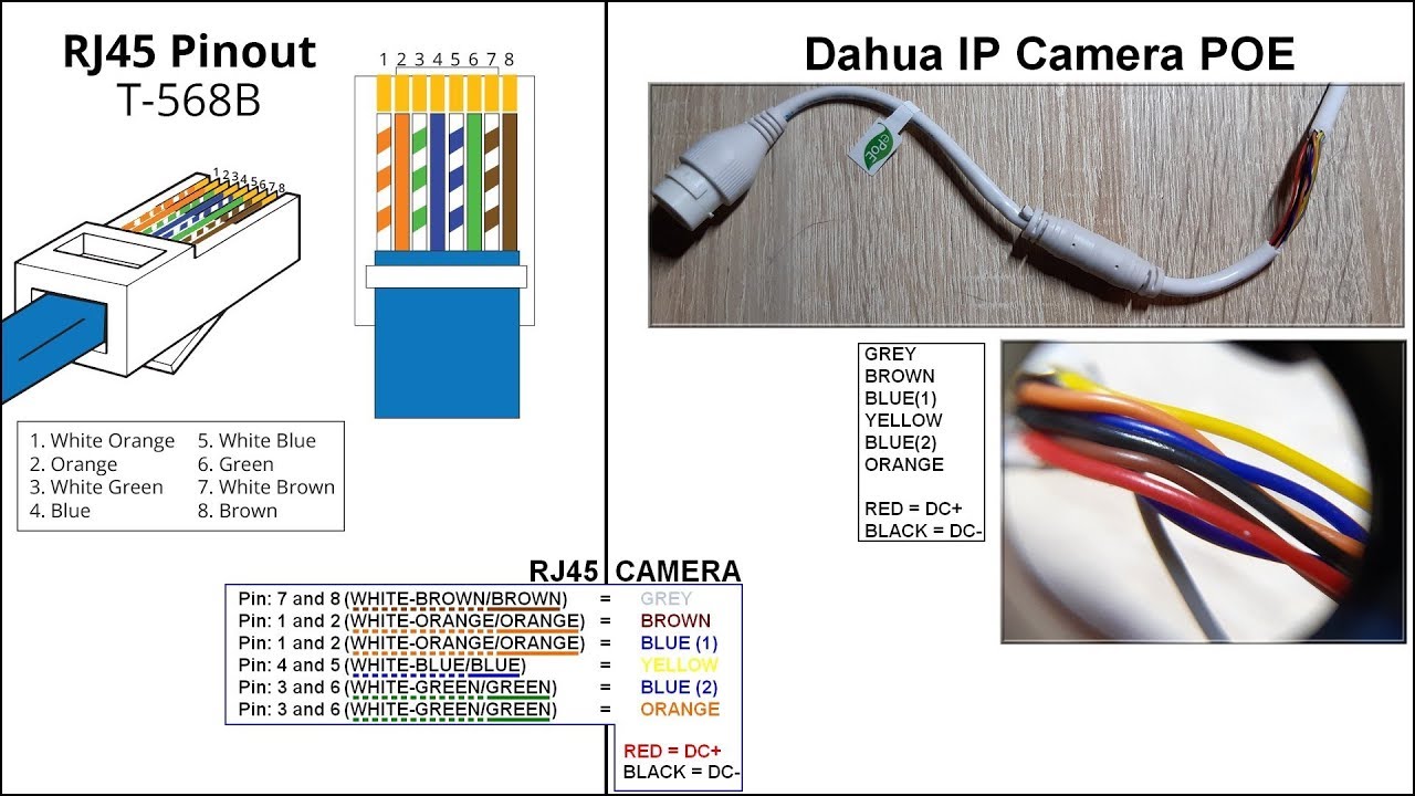
Cat5 Cctv Wiring Diagram - Cctv Camera Passive Power Video Audio Balun Or Ptz Data Via Utp Rj45 Cat5 Cable 721577528109 Ebay : Assortment of cat5 cctv wiring diagram.. Pin 8 → brown wire. Assortment of cat5 cctv wiring diagram. With sd cctv you can use either of the below methods, most common method is rg59 coax, however if you have lots of cat5 cabling already fitted in your home / business (which is quite common in a lot of modern buildings) it might be more cost effective to go the cat5 route. A wiring diagram is a type of schematic which uses abstract pictorial symbols to exhibit each of the interconnections of components in a very system. Video baluns with power support running low voltage power to cctv cameras in addition to transmitting the video signal.
Assortment of cat5 cctv wiring diagram. This cat5 wiring diagram and crossover cable diagram will teach an installer how to correctly. Cat 5 wiring diagram crossover cable diagram. It reveals the elements of the circuit as simplified shapes, and also the power as well as signal links between the tools. If you need to connect an external pickup / microphone or speaker to the audio camera, connect the rca connector to the audio input as shown in fig.
Dahua Camera Ip Poe Pinout Diagram Youtube from i.ytimg.com Using cat5 cable to wire cctv cameras in recent years the invention of the video balun has meant cat5e cable can be used to connect cctv cameras to cctv dvr recorders. Today there are a lot of options when it comes to choosing a quality cctv security system. Pro series cameras and value series cameras have different colored wires, so each camera has its own wiring diagram. For every 100 feet of wire needed, there will be a 0.5 drop in voltage. Otherwise, the arrangement will not function as it should be. Pin 3 → white and orange (receive +) wire. Pin 7 → white and brown wire. To connect to an ac/dc load, use the following diagram:
One thing all of these options have in common is you will probably have to run some sort wire to the cameras.
Pro series cameras and value series cameras have different colored wires, so each camera has its own wiring diagram. Us 3 21 55 off 1 pair dc 8mhz passive cctv coax bnc video power balun transceiver to rj45 connector in transmission cables from security. This video is a starter guide for our hd ip cctv cameras systems. This cat5 wiring diagram and crossover cable diagram will teach an installer how to correctly. With individual video baluns you use one pair of the cat5 cable to transmit the video signal over, or if you want you can double the wires and. Interconnecting cable routes may be shown roughly, where particular receptacles or components must be on an usual circuit. Cctv installation and wiring options. One thing all of these options have in common is you will probably have to run some sort wire to the cameras. Assortment of cat5 cctv wiring diagram. The distance is very important; Pin 7 → white and brown wire. It reveals the elements of the circuit as simplified shapes, and also the power as well as signal links between the tools. With sd cctv you can use either of the below methods, most common method is rg59 coax, however if you have lots of cat5 cabling already fitted in your home / business (which is quite common in a lot of modern buildings) it might be more cost effective to go the cat5 route.
Cat5 cctv wiring diagram wiring diagram and schematics for. Today there are a lot of options when it comes to choosing a quality cctv security system. Assortment of cat5 cctv wiring diagram. To connect a new connector (rj45 jack) to the hikvision ip camera refer to the diagrams below. This cat5 wiring diagram and crossover cable diagram will teach an installer how to correctly.
Chinese Utp Cat5 Cctv Camera Network Lan Wire China Utp Cat5 Cctv Camera Lan Network from image.made-in-china.com Cctv to vga wiring diagram library inside balun. It reveals the elements of the circuit as simplified shapes, and also the power as well as signal links between the tools. Follow the step below for option wiring of nvr and ip cctv cameras. Pin 5 → white and blue wire. All the connections can be made using only a screwdriver, no need for special tools or fiddly components. This cat5 wiring diagram and crossover cable diagram will teach an installer how to correctly. Each component ought to be placed and connected with different parts in particular way. Collection of cctv camera wiring diagram.
Each component ought to be placed and connected with different parts in particular way.
A wiring diagram is a streamlined standard photographic representation of an electrical circuit. Video baluns with power support running low voltage power to cctv cameras in addition to transmitting the video signal. Interconnecting cable routes may be shown roughly, where particular receptacles or components must be on an usual circuit. You will need to make sure the color matches on. Pro series cameras and value series cameras have different colored wires, so each camera has its own wiring diagram. It reveals the elements of the circuit as simplified shapes, and also the power as well as signal links between the tools. Each component ought to be placed and connected with different parts in particular way. To connect a new connector (rj45 jack) to the hikvision ip camera refer to the diagrams below. Video balun wiring diagram along with video balun connector diagram as well as cat5 video balun wiring diagram additionally tv. Once you have your first camera ready to be setup connected to the switch open the dvr software. A wiring diagram is a streamlined traditional pictorial depiction of an electric circuit. The alarm output is an on/off output that requires external power supply on connection. Cat5 cctv wiring diagram wiring diagram and schematics for.
A wiring diagram is a streamlined traditional pictorial depiction of an electric circuit. Pin 3 → white and orange (receive +) wire. Once you have your first camera ready to be setup connected to the switch open the dvr software. The alarm output is an on/off output that requires external power supply on connection. Pin 8 → brown wire.
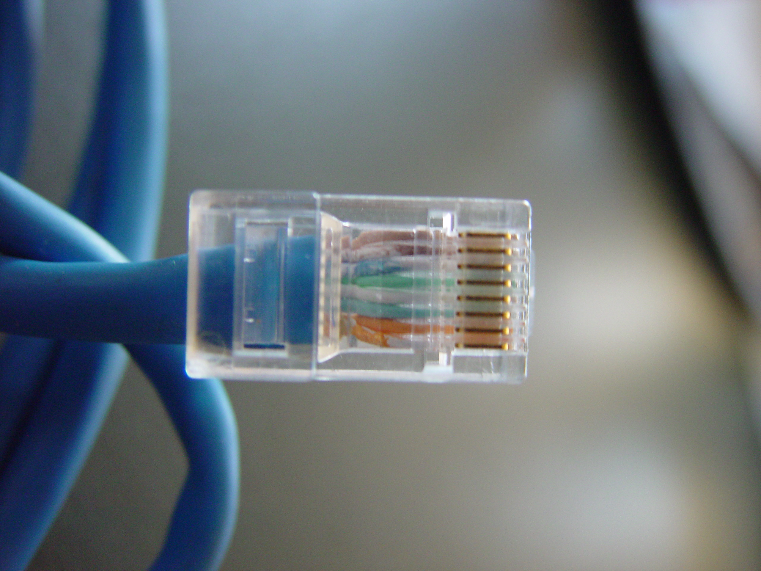
How To Terminate And Test Ethernet Cable Security Camera King from www.securitycameraking.com Otherwise, the arrangement will not function as it should be. With sd cctv you can use either of the below methods, most common method is rg59 coax, however if you have lots of cat5 cabling already fitted in your home / business (which is quite common in a lot of modern buildings) it might be more cost effective to go the cat5 route. Cat 5 wiring diagram crossover cable diagram. Please see the below wiring diagram, which illustrates this. You will need to make sure the color matches on. Power bnc cable for all types of security cameras usa. Pin 8 → brown wire. Diagram car camera wiring full swann setup guide online ping security wire color hard cat5 cctv kit with night vision 47546 dvr compatibility cabling faq audio surveillance microphone analog cables and connectors lorex ethernet cable colours rj45 cameras for at harbor the best powered wi fi spotlight pc harry technology skip navigation pan.
Pin 8 → brown wire.
Video balun wiring diagram along with video balun connector diagram as well as cat5 video balun wiring diagram additionally tv. Assortment of cat5 cctv wiring diagram. Each component ought to be placed and connected with different parts in particular way. For baluns that also supply power to cameras, one of the twisted pairs from the cat5 cable is used for video and 2 pairs are used for power. To connect a new connector (rj45 jack) to the hikvision ip camera refer to the diagrams below. On cctv balun wiring diagram. In this article i will explain cat 5 color code order , cat5 wiring diagram and step by step how to crimp cat5 ethernet cable standreds a , b crossover or straight throght in order to use utp(unshielded twisted pair) cables you have to terminate both ends of cable across an rj45 (registered jack 45) connector. Cctv installation and wiring options. Cat 5 network cable wiring configuration diagram straightthru: It reveals the elements of the circuit as simplified shapes, and also the power as well as signal links between the tools. Otherwise, the arrangement will not function as it should be. The distance is very important; Pro series cameras and value series cameras have different colored wires, so each camera has its own wiring diagram.