What Is A Wiring Diagram - Wiring Diagram Edrawmax - Basics 13 valve limit switch legend :. Wiring diagrams can be helpful in many ways, including illustrated wire colors, showing where different elements of your project go using electrical symbols, and showing what wire goes where. Additionally, what are the two types of wiring diagrams? To read it, identify the circuit in question and starting at its power source, follow it to ground. The usage of wiring diagram In the trailer wiring diagram and connector application chart below, use the first 5 pins, and ignore the rest.
Wiring diagram a wiring diagram is sometimes helpful to illustrate how a schematic can be realized in a prototype or production environment. Color code for wiring diagram. Wiring diagrams show how the aircraft wires are connected and where they should be located in the electrical system, as well as the physical connections between all the components. It shows how the electrical wires are interconnected and can also show where fixtures and components may be connected to the system. Posted on august 2, 2012 by janpenguin.
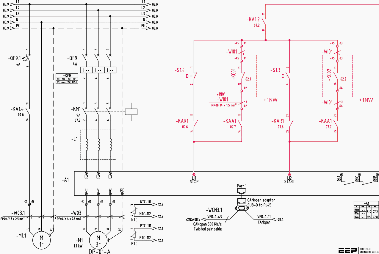
The Wiring Diagram And Physical Layout Of The Equipment Inside The Motor Control Centre Eep from electrical-engineering-portal.com Wiring diagram a wiring diagram is sometimes helpful to illustrate how a schematic can be realized in a prototype or production environment. It shows the components of the circuit as simplified shapes, and the power and signal connections between the devices. There are two main options as shown in the schematic above. Wiring diagrams electrical wiring diagrams are included in most aircraft service manuals and specify information, such as the size of the wire and type of terminals to be used for a particular application. B black br brown ch chocolate dg dark green g green gy gray l blue lg light green o orange p pink red red sb sky blue w white y yellow b/g black/green b/l black/blue b/r black/red b/w black/white b/y black/yellow br/g brown/green A wiring diagram is a simple visual depiction of the physical links and physical layout of an electrical system or circuit. You can bring the cables from all wall sockets to a central location. A wiring diagram is a simplified conventional pictorial representation of an electrical circuit.
A wiring diagram is a simple visual depiction of the physical links and physical layout of an electrical system or circuit.
The receptacle is split by breaking the connecting tab between the two, brass colored terminals. I'm an auto technician for over twenty years, i've always loved the electrical side of auto repair. Basics 9 4.16 kv pump schematic : The other option is to use several switches perhaps one per floor and wire those switches back to a central location. When and how to use a wiring diagram It shows the components of the circuit as simplified shapes, and the power and signal connections between the devices. A circuit diagram behind a circuit board. The power supply is shown at the top and the earth at the bottom to facilitate understanding of the current flow. The wiring diagram shows different components in a circuit via different shapes and symbols. A wiring diagram is a simplified conventional pictorial representation of an electrical circuit. Wiring diagram a wiring diagram is sometimes helpful to illustrate how a schematic can be realized in a prototype or production environment. A wiring diagram usually gives information about the relative position and arrangement of devices and terminals on the devices, to help in building or servicing the device. A wiring diagram is a visual representation of components and wires related to an electrical connection.
Basics 10 480 v pump schematic : When and how to use a wiring diagram We are going to do our best to simplify that, mainly with a good, color coded diagram. For example, the electrical wiring diagrams may show you which wires to connect to replace a light fixture, or which wires to use if you need to add a plug outlet. Let's have a look at their differences with the help of a table.
Electrical Wiring Diagram And Electrical Circuit Diagram Difference Etechnog from 1.bp.blogspot.com A car wiring diagram is a map. The tab between the neutral, silver terminals should remain intact. B black br brown ch chocolate dg dark green g green gy gray l blue lg light green o orange p pink red red sb sky blue w white y yellow b/g black/green b/l black/blue b/r black/red b/w black/white b/y black/yellow br/g brown/green What is a wiring diagram? Basics 9 4.16 kv pump schematic : Download the guide below, print it and keep it in your toolbox for future reference. A wiring diagram is a simplified conventional pictorial representation of an electrical circuit. Basics 10 480 v pump schematic :
Basics 8 aov elementary & block diagram :
Also called wiring diagrams or circuit diagrams, these diagrams show how the different components of a circuit are connected.in these diagrams, lines represent connecting wires, while other elements like resistors, lamps, and switches are represented by. In the trailer wiring diagram and connector application chart below, use the first 5 pins, and ignore the rest. When and ways to make use of a wiring diagram The power supply is shown at the top and the earth at the bottom to facilitate understanding of the current flow. It shows just how the electrical wires are adjoined and also could also reveal where components and components could be connected to the system. A wiring diagram is mainly intended to convey the wiring or connection between the components in a proper way without any confusion, so that one can create a prototype easily using that. If your vehicle is not equipped with a working trailer wiring harness, there are a number of different solutions to provide the perfect fit for. This is the option shown in most home wiring videos on youtube. Types of electrical diagrams or schematics they are wiring, schematic, and pictorial diagrams. Basics 13 valve limit switch legend : Let's have a look at their differences with the help of a table. The tab between the neutral, silver terminals should remain intact. A proper wiring diagram will be labeled and show connections in a way that prevents confusion about how connections are made.
The power supply is shown at the top and the earth at the bottom to facilitate understanding of the current flow. A wiring diagram is a simple visual depiction of the physical links and physical layout of an electrical system or circuit. A wiring diagram is mainly intended to convey the wiring or connection between the components in a proper way without any confusion, so that one can create a prototype easily using that. The wiring diagram shows different components in a circuit via different shapes and symbols. The usage of wiring diagram
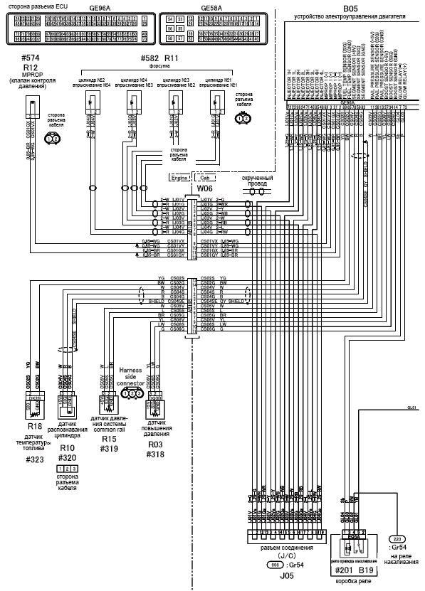
Mitsubishi Wire Diagram Wiring Diagram Data Producer from image.jimcdn.com It shows how the electrical wires are interconnected and can also show where fixtures and components may be connected to the system. Wiring diagram for a split outlet. They are crucial to the assembly of the circuit or system. The usage of wiring diagram Let's have a look at their differences with the help of a table. Types of electrical diagrams or schematics they are wiring, schematic, and pictorial diagrams. This diagram illustrates the wiring for a split receptacle with the top half controlled by sw1 and the bottom half always hot. A wiring diagram is a simplified conventional pictorial representation of an electrical circuit.
This diagram illustrates the wiring for a split receptacle with the top half controlled by sw1 and the bottom half always hot.
This diagram illustrates the wiring for a split receptacle with the top half controlled by sw1 and the bottom half always hot. A circuit diagram behind a circuit board. Types of electrical diagrams or schematics they are wiring, schematic, and pictorial diagrams. The purpose of a wiring diagram can be to assist in either the construction or repair of an electronic device. A wiring diagram is mainly intended to convey the wiring or connection between the components in a proper way without any confusion, so that one can create a prototype easily using that. The first type of electrical wiring diagram is a diagram that shows you how to actually complete certain simple electrical projects. A wiring diagram is a simplified conventional pictorial representation of an electrical circuit. Wiring diagrams, or layouts, illustrate the physical connections, or wiring, between components. A wiring diagram is a simple visual depiction of the physical links and physical layout of an electrical system or circuit. A wiring diagram is a simple visual representation of the physical connections and physical layout of an electrical system or circuit. This is the option shown in most home wiring videos on youtube. The receptacle is split by breaking the connecting tab between the two, brass colored terminals. A wiring diagram is a simplified conventional pictorial representation of the physical connections and physical layout of an electrical system or circuit.